
The following points in flying by means of the aeroplane must be cleared, either by study of the past efforts of others, or by personal experiments: The supporting power of the air, the resistance to a forward movement in it, the extent in ' square feet of the supporting surface, the form of the flying machine, the material of which it is to be built, the power of the motor to be employed, whether propellers or moving wings are to be used, the form of rudders or other expedients for effecting the steering and starting, the maintenance of the equiilbrium, and the plan of safely alighting.
The supporting power of the air has been determined. Prof. S. P. Langley, of the Smithsonian Institution, Washington, D. C., sustained under favorable conditions by aeroplane a maximum of 200 pounds per horse-power expended. This result was reached by placing the aeroplanes at the end of a long arm revolving about a fixed center. Hiram Maxim, Mr. Hargrave, and others have constructed motors weighing less than 10 pounds for each horse-power developed. Propulsion and lifting power are solved problems, and it is obvious that there is the margin between 10 pounds and 200 pounds to carry the weight of the aviator and the flying machine. Care and attention must therefore be devoted to the general form of the machine, with the object of obtaining automatic equilibrium and safe support.
After numerous experiments with models, many of them on different lines from any previously, constructed and many of them very successful and encouraging, I have begun and nearly completed the construction of a full-size flying machine. It is built on the aeroplane principle, that is, it has no gasbag or balloon to support it, but is supported in air only when in motion, and by the upward reaction of the air upon the underside of thin fixed surfaces or aeroplanes, which are slightly inclined to the line of motion.
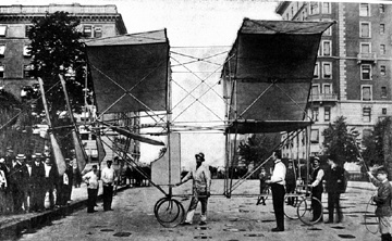
Side View
of the Ludlow Aeroplane,
Showing Arrangement of Supporting Planes,
Rudder, and Propellers.
The framework is of light bamboo, of one and one-quarter inches, and is covered with light canvas treated with a preparation of boiled linseed oil and a drier. The joints are bolted with 3/16-inch bolts, and bound with light yacht marlin. There are two groups of three superimposed aeroplanes placed by pairs in tandem fashion. A large supporting surface with a manageable area and less weight of frame is gained by using superimposed aeroplanes in this manner. The two halves of each of the two middle aeroplanes are set at a diedral angle with each other.
The upper forward aeroplane is a trapezoid in shape. Its forward edge is 13 feet in length, its rear edge is 18 feet. Its sides are 7 feet 3 inches in length, and it has a depth of 6 1/2 feet. The middle front aeroplane forms a diedral angle with the top of its sides reaching the upper aeroplane, and its two halves are 1/2 feet long, with a depth of 6 1/2 feet The lower front aeroplane is rectangular in shape, and has a width of 10 feet and a depth of 6 6 1/2 feet. The open space dividing the two sets of aeroplanes is 6 feet wide.
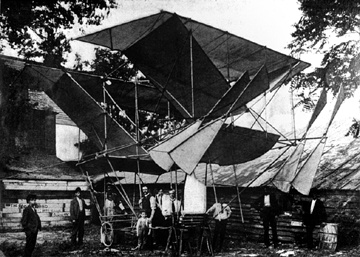
Stern View of the
Ludlow Aeroplane,
Showing Double Set of Propellers.
The upper rear aeroplane is rectangular in shape, and 21 feet by 6 1/2 feet in width and depth. The two halves of the middle or diedral angle rear aeroplane are each 11 feet wide by 61/2 feet in depth. The lower rear aeroplane is rectangular in shape, and 9 feet by 61/2 feet in width and depth.
There is a total of 556 1/4 square feet of surface; but as the supporting surface of the diedral angle aeroplane is not greater than the horizontal projection of such diedral angle aeroplane, the supporting surface is calculated at 491 1/4 square feet. These diedral angle aeroplanes give direction to the line of flight, prevent oscillation, and overcome a tendency of the machine to turn around on its center of gravity. They also give lateral stability; for when the machine tilts, the halves of the diedral angle of the aeroplanes which are down are more horizontal than those on the other side, and receive consequently greater air pressure, and the equilibrium of the flying machine is recovered.
Longitudinal equilibrium is gained by dividing the air current that passes the under surface of the aeroplanes. It is apparent that any upward or downward tendency of either the fore or aft aeroplanes is counterbalanced by the opposite effects on the other planes. The light connecting rod crossing the open space between the fore and aft aeroplanes forms the fulcrum upon which this force of the wind acts.
The inclosed triangular chamber formed by the diedral angles of the middle aeroplane with the upper aeroplanes gives direction to the air current passing through them, and imparts additional steadiness to the flying machine. The edges of the diedral angle aeroplanes not extending to the edges of the two upper aeroplanes, a further improvement in the stability is gained by leaving the same yielding and elastic under pressure.
The position of the aviator, as that of the motor, is below the aeroplanes. This brings the center of gravity below the center of pressure By a simple arrangement of levers in connection with the lower front aeroplane, which also is a rudder acting horizontally, automatic equilibrium is imparted to the flying machine by the shifting of the position of the aviator caused by the tilting of the flying machine upward or downward. This pendulum motion of shifting the center of gravity with reference to the center of pressure can be enlarged at will, and made to correspond to the change in the center of pressure produced by the alteration in the angle of incidence or by greater speed, and assists the efforts of the horizontal rudder to correct the undue tendency to ascend or descend.
The machine is mounted on four wheels, the two front ones being capable of guidance. This arrangement permits alighting at an acute angle and rolling upon the ground until momentum is exhausted; or to gain headway by running along the ground before starting in flight
My weight is 167 pounds. The weight of the flying machine without the motor is 165 pounds. The motor will weigh about 75 pounds. Giving a total weight of 307 pounds, or 1.6 square feet of surface for each pound of weight to be lifted. That this proportion of square feet of surface to pounds in weight is most desirable, was verified by many experiments with models and man-lifting kites.
Examples of this sort in nature are not very conclusive. The dragon-fly and the gnat; if their proportions were magnified until each weighed a pound, would have 25 and 50 square feet of surface respectively. The condor, the largest soaring bird, weighs 17 pounds and has less than 10 square feet of supporting area. The ratio of the wing surface of the swallow to its weight is about 3 1/2 to 1. The giant petrel (Procellaria gigantea) a wonderful example of long sustained flight, with at times absolutely motionless wings, has a ratio of 1.56 square feet of surface to each pound of weight and is supposed to expend less than 5/100 of a horse-power of effort to keep itself afloat in the air.
At an angle of flight of ten degrees, the air reaction, according to the table compiled by Prof. S. P. Langley, from the result of exhaustive experiments, in which experiments he was aided by an appropriation from the United States government, is 30 per cent of the normal pressure of the air striking the plane at an angle of 90 degrees.
At a velocity of 30 miles an hour, or 2,640 feet per minute, the wind, according to Smeaton's formula, exerts a pressure on a plane at right angles to the current of 4.5 pounds to each square foot of surface. The supporting power of the flying machine running at 30 miles an hour will therefore be 491 1/4 times 4.5 times 0.30, or 662.85 pounds sustained. Inasmuch as the total weight to be lifted is less than half that figure, and as neither the drift nor the body, the edge of the wings, braces or other resistance will require that large margin of resistance, it is likely that a less speed or a smaller angle of incidence to horizontal progression will be sufficient.
There are two propellers of four blades each, 8 feet in diameter, and varying in width from 5 inches to 18 inches at the extreme edge. The skeleton structure of the propellers is of bamboo, and is covered with light oil canvas. The blades are in pairs, one behind the other, and connected together with diagonal struts and ties, so that in motion the members of one blade will be in compression and the other in tension.
While I have made application for letters patent for various parts of my flying machine, I have no desire to preclude anyone else experimenting along the same lines, and it is because I believe for the general advancement of the science that one should communicate results with others who may be interested in the same field, that I make public these experiments. It will be pleasant to record success at the trial, but progress in this science has so far been built upon failures. If, however, the flying machine should not fly, it will be no reason why this research should be abandoned, for success is often built on failures.
Originally appeared in Scientific American, 93, July 15, 1905, p. 45.
sbck/htgb