
No. 17 flying machine of M. Hargrave is described in his twelfth comnnunication to the Royal Society of New South Wales, read August 3, 1892. The total weight of the apparatus is 64.5 oz, or 4.03 lbs., including 12 3/4 oz. for the strut and body plane, so that the engine and boiler, including 5 oz. for spirit fuel and water, weighs 3.25 lbs., and develops 0.169 horse power, or at the rate of 1 H.P. per 19.2 lbs.--a very remarkable achievement.
The boiler is of the "Serpollet" type, made of 12 lineal feet of 1/4 in. copper tubing (steel pipe could not be got in Sydney), in the form of a double-stranded coil, encased in asbestos, and placed just over the backbone of the apparatus. The fuel is methylated spirits of wine, drawn from a tank placed above the boiler, vaporized, mixed with air and spurted into the furnace. As much as 6 .9 cub. in. of water have been evaporated by 1.7 cub. in. of spirit in 80 seconds, making 182 double vibrations of the propelling wings, say, 2.35 per second, and developing 0.169 horse power.
It was estimated that if the apparatus were loaded with 10 oz. more of spirit and water, and thus made to weigh the same as the compressed-air machine No. 12, which flew 343 ft., then the steam apparatus No. 17 would possess a sufficient store of energy to fly 1640 yds., or nearly 1 mile.
But M. Hargrave has done still better, for in March 1893, he prepared a paper, which was presented to the Conference on Aerial Navigation at Chicago, August 2 1893 in which he gave data concerning his No. 18 flying machine. This apparatus is also driven by a steam-engine which weighs, with 21 oz. of fuel and water, an aggregate of 7 lbs, and indicates 0.653 horse power, or at the rate of 10.7 lbs. per horse power; so that, roughly speaking, the weight of the motor has been doubled, and the power has been increased fourfold.
Four boilers were constructed. The final one was made of 21 lineal feet of 1/4 in. copper pipe, with an internal diameter of 0.18 in., and arranged in three concentric vertical coils whose diameters were 1.6 in., 2.6 in., and 3.6 in. respectively. It weighed 37 oz., but it is now known "that a coil of equal capacity can be made weighing only 8 oz, and still excessively strong." The cylinder is 2 in. diameter with a stroke of 2.52 in. The feed-pump ram is 0.266 in. diameter, and the piston valves 0.3 in. diameter. On one occasion this motor evaporated 147 cub. in. of water with 4.13 cub. in. of spirit in 40 seconds. During a portion of the time it was working at a speed of double vibrations per minute.
M. Hargrave gives no data concerning the flight of his last two (steam) machines. He states that 11 different burners have been tried, and that the flame striking the water boiler first has a tendency to vary the supply of heat to the spirit holder. From this it is inferred that he is struggling with the same difficulties already encountered by Stringfellow, by Moy, and by Maxim in regulating and keeping alight spirit burners when the apparatus gets under forward head-way; but this difficulty, while a serious one, will doubtless be eventually overcome by persistent experiment, and we may then expect flights of astonishing lengths.
Seeing now his way to an adequate motor and to extensive flights in the near future, M. Hargarve recently turned his attention to experiments upon curved surfaces, and to the seeking for a better disposition of the sustaining surfaces or body planes. He had described the eccentricities of a curved strip in the form of a segment of a hollow cylinder, when exposed to the wind, in his paper No. 12 to the Royal Society of New South Wales, read August 3, 1892 and he describes some of his experiments with "cellular kites," in his paper read in the Aerial Navigation at Chicago, August 2 1893.
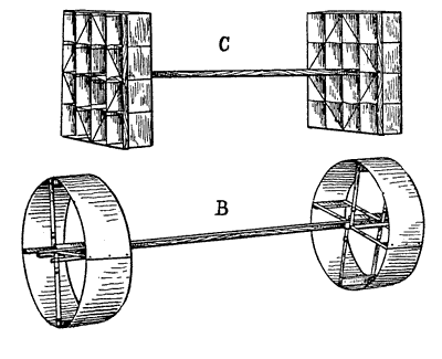
FIG. 80 -- HARGRAVE -- 1893.
The "cellular kites" constitute quite a new departure, and practically consist of superposed aeroplanes connected together in pairs. B, in fig. 80, shows the simplest form. This consisted of two hollow cylinders of aluminum, each 13 in. diameter by 4 1/2 in. deep, mounted 30 in. apart upon a connecting stick, and weighing 14 3/4 lbs. The kite-string was attached 11 in. back from the forward section, and as a consequence of the angle of incidence thus produced, the apparatus mounted upon the wind. Its particular behavior is not described in the paper. C, in fig. 80, shows a kite with 16 cells, the length of each being 3 in., by a height of 3 in., and a breadth of 3 in. It was made of cardboard, and the two sections were 22 in. apart, the point of attachment of the kite-string being 6 1/2 in. distant from the forward section, while the weight was 10.5 lbs. This seems to indicate that this kite flew at a steeper angle than the preceding, although we should expect the reverse, in consequence of the greater proportion of sustaining surface. M. Hargrave says, "These kites have a fine angle of incidence, so that they correspond with the flying machines they are meant to represent, and differ from the kites of our youth, which we recollect floating at an angle of about 45 , in which position the lift and the drift are about equal. The fine angle makes the lift largely exceed the drift, and brings the kite so that the upper part of the string is nearly vertical."
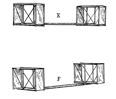
FIG. 81 -- HARGRAVE-- 1893.
Kites E and F, fig. 81, are of exactly the same size and weight, consisting of one cell, 4 in. long, 10.7 in. broad by 6.25 in. high, constructed of wood and paper, and weighing 3.25 lbs.; the two sections are 21.25 in. apart, and the string is fastened 7.25 in. back of the forward section. The only difference is that kite E has its horizontal (top and bottom) surfaces curved to a radius of 4.5 in. while all the surfaces of kite F are true planes, The result is that when kite E is flown with the convex sides up it pulls about twice as hard on the string as kite F, so that, as M. Hargrave says: "A flying machine with curved surfaces would be better than one with a net body plane, if the form could be made with the same weight of material."
M. Hargrave, in this last paper, figures and describes two other forms of cellular kites with which he has experimented, and points out that the rectangular form of cell is collapsible when one diagonal tie is disconnected. so as to make it easy of transportation. He says: "Theoretically, if the kite is perfect in construction and the wind steady, the string could be attached infinitely near the center of the connecting stick, and the kite would fly very near the zenith. It is obvious that any number of kites may be strung together on the same line, and that these is no limit to the weight that may be buoyed up in a breeze by means of light and handy tackle. The next step is clear enough--namely, that a flying machine with acres of surface can be safely got under way, or anchored and hauled to the ground by means of the string of kites."
He duly gives credit to M. Wenham for suggesting the superposition of planes in 1866 and it is an interesting circumstance to note that at the same Chicago Conference, a paper from M. Wenham was read suggesting a course of experiments with kites, to determine the best arrangement of superposed aeroplanes and the conditions of equipoise.
Such are the labors of M. Hargrave up to the present time. He no longer troubles himself about the general problem of man's eventual success in navigating the air, but he says: "The people of Sydney who can speak of my work without a smile are very scarce; it is doubtless the same with American workers. I know that success is dead sure to come, and therefore do not waste time and words in trying to convince unbelievers."
Instead of this, he constructs machines and reports the results in detail, so that others may repeat his experiments. He e says that the record of unsuccessful experiments takes up a considerable portion of kits notes, and further, that "there is no use in the mind's conceiving an idea, if the hands are not ready to carry out the work skillfully, in the absence of reliable assistance, and if the design be found faulty, the whole thing should be begun again without trying to use up old machines. The question of intricate workmanship and costliness is being continually battled with; my constant endeavors are directed to making the machines simple and cheap, so that any one who doubts can verify my work, provided his hands are as skillful as mine, and I am sure that the photographs show clearly that the workmanship is anything but first-rate.
He began with small, cheap models, and has gradually enlarged their size, and obtained flights longer than any heretofore accomplished. It is noticeable that the heavier the model, and the smaller the sustaining area in proportion to the weight, the more successful has been the flight. He may not be the first man to ride at will upon the air, but he deserves to succeed.
In November, 1890, M. Hiram S. Maxim the celebrated American inventor of a writing telegraph, of several systems of electric lighting, and of the "Maxim automatic machine gun," addressed a letter to the New York Times in which he stated that, before sailing back to England, he thought it would be well to state what he was doing toward constructing a flying machine which had been alluded to lately by the American press. Among other things he said:
I would say that among the large number of societies to which I belong in England, the Aeronautical Society is one, and need I say that I am the most active member? At the present moment experiments are being conducted by me at Baldwin's Park, Bexley, Kent, England, with a view of finding out exactly what the supporting power of a plane is when driven through the air at a slight angle from the horizontal. For this purpose I constructed a very elaborate apparatus, provided with a great number of instruments, and arranged in such a manner that I can ascertain accurately the 'efficiency of a screw working in air. the amount of power required to drive a screw, the amount of push developed by a screw, the amount of slip, and also the power required for propelling planes through the air when placed at different angles, as well as to ascertain the friction and all other phenomena connected with the subject. I have been experimenting with motors and have succeeded in making them so that they will develop I horse power for every 6 lbs. My experiments show that as much as 133 lbs. may be sustained in the air by the expenditure of 1 horse power; of course. it is premature now to express any opinion; still, if I am not very much mistaken, and if some new phenomenon, which I do not understand, does not prevent it, I think I stand a fair chance of solving the problem, and I think I can assert that within a very few years some one--if not myself, somebody else--will have made a machine which can be guided through the air, will travel with considerable velocity and will be sufficiently under control to be used for military purposes. I have found in my experiments that it is necessary to have a speed of at least 30 miles per hour, that 50 miles is still more favorable, and that 100 miles would seem to be attainable. Everything seems to be in favor of high speed.Whether I succeed or not, the results of my experiments will be published, and as I am the only man who has ever tried the experiments in a thorough manner with delicate and accurate apparatus, the data which I shall be able to furnish will be of much greater value to experimenters hereafter than all that has ever been published before.
In May 1891 M. Maxim again visited the United States, and he gave to various newspaper reporters, notably to one from the New York Sun, some particulars concerning the flying machine, or "first kite of war," which he was building in England, and upon which he had spent up to that time (including the preliminary experiments) some $45,000.
He described the apparatus with which he had made his preliminary experiments, to ascertain accurately the supporting power and resistance of air to aeroplanes at small angles of incidence, and then continued as follows:
My large apparatus is provided with a plane 110 ft. long and 40 ft. wide, made of a frame of steel tubes covered with silk. Other smaller planes attached to this mane up a surface of 5500 sq. ft. There is one great central plane, and to this are hinged various other planes, very much smaller, which are used for keeping the equilibrium correct, and for keeping the flying machine at a fixed angle in the air. The whole apparatus, including the steering gear, is 145 ft. long. . . . A part of the aeroplane, or actual kite, is made of very thin metal, and serves as a very efficient condenser for the steam.It is ready and awaiting my return. It is now resting on a track 8 ft. wide and half a mile long. in my park. The first quarter of a mile of the track is double--that is to say, the upper track is 3 in. above the lower. By that means I am able to observe and measure the lift of the machine when it starts, because the upper track will hold it down when it lifts off the lower one. When completed the machine will weigh, with water tanks and fuel, somewhere between 5,000 lbs. and 6,000 lbs., and the power at my disposal will be 300 horse power in case I wish to use it; but it is expected that about 40 horse power will suffice after the machine has once been started, and that the consumption of fuel will be from 40 lbs. to 50 lbs. per hour. The machine is made with its present great length so as to give a man time to think; its length makes it easier to steer and to change its angle in the air. Its quantity of power is so enormously "real in proportion to its weight that it will quickly get its speed It will rise in the air like a sea-gull if the engine begun at full speed while the machine is held fast 10 the track, and if it is then suddenly loosened and let go.
M. Maxim very judiciously refrained from furnishing drawings or detailed descriptions of an apparatus which was still in process of evolution, and which he might want to modify as he proceeded in erection and trial. Indeed, it is probable that he has varied considerably from the various arrangements which he has patented from time to time,39 so that drawings and descriptions made from these might be wide of the mark.
The important, the vital feature, however, he recognized to be the motor, and to perfecting this he gave kits first attention. In steam motors he seems to have accomplished wonderful results, hitherto quite unreached, and in an article published in the Century Magazine for October, 1891 after describing and illustrating the experimental whirling machine with which he had gathered his preliminary data, he gives the following account of what he had accomplished up to that time with the motor:
I have come to the conclusion that the greatest amount of force with the minimum amount of weight can be obtained from a high-pressure compound steam engine, using steam at a pressure of from 200 lbs to 350 lbs. to the square inch, and lately I have constructed two such engines, each weighing 300 lbs. These engines, when working under a pressure of 200 lbs. to the square inch, and with a piston speed of only 400 it. per minute, develop in useful effect in push of screws over 100 horse power, the push of the screws collectively being over 1000 lbs. By increasing the number of turns, and also the steam pressure. I believe it will be possible to obtain from 200 horse power to 300 horse power from the same engines, and with a piston speed no greater than 850 ft per minute.40 These engines are made throughout of tempered steel, and are of great strength and lightness. The new feature about my motors however is the manner of generating steam. The steam generator itself, without the casing about it, weighs only 350 lbs.; the engine, generator, casing, pumps, cranks, screw shaft, and screws weight 1,800 lbs., and the rest of the machine as much more. With a supply of fuel, water, and three men the weight will not be far from 5,000 lbs. As the foregoing experiments have shown that the load may be 14 times the push of the screw, it would appear that this machine ought to carry a burden, including its own weight, of 14,000 lbs., thus leaving a margin of 9000 lbs, provided that the steam pressure is maintained at 200 lbs. to the square inch. The steam generator is sell-regulating, has 48,000 brazed joints and is heated by 45,000 gas jets, gas being made by a simple process from petroleum. When the machine is finished the exhaust steam will be condensed by an atmospheric condenser made of a great number of very thin metallic tubes, arranged in each a manner that they form a considerable portion of the lifting surface of the aeroplane. The greater part of the machine is constructed from thin steel tubes. I found that these were much more suitable for the purpose than the much-talked aluminium; still I believe that if I should succeed in constructing a successful machine, it would lead to such improvements in the manufacture of aluminium products that it will be possible to reduce greatly the weight of the machine.The question of keeping the machine on an "even keel," of steering, and of landing, has been duly considered and provided for, hut a description of these would be premature before the machine has actually been tried.
When it is remembered that locomotives weigh some 200 lbs. per horse power, that the lightest marine (launch) engines in 1889 weighed about 60 tbs. per horse power, and that the largest steam-engines previously built for aerial navigation purposes were those of Giffard and of Moy each of 3 horse power and weighing (with their boilers) 110 lbs. and 27 lbs. per horse power respectively, then the importance of M. Maxim's achievement as above set forth, may be partially realized, particularly when it is considered the! the relative weight tends to increase with the size, and that M. Maxine's expectations of obtaining 300 horse power from the same engines have been fully confirmed, as will be seen hereafter.
Moreover, as exhausting the steam into the air would involve carrying a supply of water amounting to some 20 or 25 lbs. per horse power per hour, and this would have been simply prohibitory, M. Maxim's plans included a surface aero-condenser. in order that the same water might be used over and over again. This was a wholly unsolved problem. such tentative experiments as had been tried previously by others having indicated weights of 50 lbs. to 150 lbs. per horse power, as necessary for efficient aero-condensers, and. this would also have been prohibitory.
M. Maxim proposes to solve this problem by making all the frames of his apparatus of hollow tubes, and connecting therewith a condenser consisting of a large number of wide, flat, or film tubes--that is to say, of tubes of thin metal having a flat bore, through which the steam will pass in thin films of considerable width, these film tubes being so arranged that in the forward motion of the machine the air will impinge upon them, thus effectually cooling them and condensing the steam therein. This aero-condenser is utilized as a part or the whole of the sustaining surface, or there may be substituted there for a large flexible bag or chamber, connected at the forward part with the exhaust steam-pipe, and at the rear end with the hot well, or directly with the suction pipe of the feed pump. He relies, of course, upon the increased condensation produced by air currents due to the forward motion of the machine, and the extent of the condenser is therefore a matter for experiment, so that its exact weight cannot be settled in advance.
The horizontal angle of incidence in flight is to be maintained by a "Gyrostat," which consists in a gyroscopic wheel rotating rapidly, suspended by universal joints and connected with two horizontal rudders, one at the front and the other at the back of the apparatus, so as to act upon them instantly (through the well-known property of the gyroscope to continue rotating in the same plane), in case any tendency occurs to deviate from the angle of incidence with the horizon.
The whole of the apparatus is to be thoroughly stayed by diagonal wire ties, so as to make every part rigid and prevent deformations under varying wind pressures.
Fig. 82 engraved from a photograph kindly furnished by M. Maxim, exhibits the main features of the apparatus. It does not show the front or back rudders, which have been removed, nor the side wings, set at a diedral angle, to preserve the transverse stability nor sundry possible keel-cloths or auxiliary planes intended to promote the same object. It exhibits the central or principal aeroplane, with the forward end facing the observer. This main aeroplane is understood to be 50 ft. wide, about 58 ft. long, and slightly concave in the direction of its length, while it is trussed and stiffened in every direction by wire stays. The condenser is indicated by the dark shading at the front of the main plane, and, as will readily be seen, can be largely increased in surface, but, however, at the expense of added weight. The driving screws are placed at the rear, and are understood to be 17 ft. 10 in. in diameter, the speed of rotation varying, of course, with the power exerted.
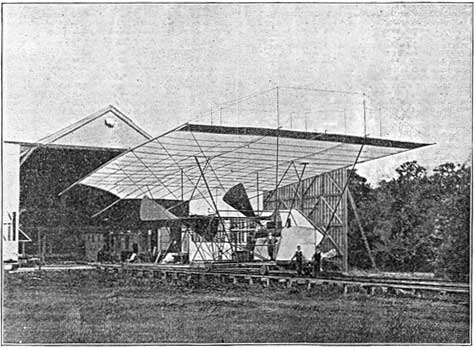
FIG. 82. -- MAXIM -- 1892.
The whole apparatus is mounted upon wheels, running over a railway track, so as to acquire sufficient speed to rise upon the air, and the three men who are grouped about the front may enable the reader to gather by comparison some general conception of the colossal dimensions of this flying machine.
39 British patents Nos. 10,359
and 16.883 A.D. 1889 No. 19.228 A.D. 1891
40 The piston speed
of an express locomotive is about 1000 ft. per minute.
| List of Illustrations | Table of Contents | Index |