
But these wonderful performances of the "sailing birds" are chiefly witnessed in tropical or semi-tropical regions -- those in which the steady trade winds or the regularly incoming sea breezes afford daily to the birds the power of performing their evolutions in search of food. In the more temperate regions the wind does not blow every day with just the right intensity, the casual soaring bird is frequently compelled to resort to flapping, and the would_be inventor has his thoughts directed to some form of a power machine; generally some combination of aeroplanes with propelling screws, which differs a good deal from the simple. compact, and severe outlines indicated by nature.
The form of the soaring bird is reducible to three elements. First, a comparatively large body, shapely, but unsymmetrical fore and aft, presumably the solid of least resistance to the air; second, a symmetrical pair of wings, convex on top, and more or less concave beneath, with a sinuous and stiff front edge; and, third, a tail, which varies greatly in its proportion among the various species. For these features, most of the inventors have substituted a small, boat-like body, a combination of flat planes and flat rudders, both horizontal and vertical, which last is not found to exist in the bird.
A good case in point is found in the instance of Mr. Krueger, who patented in the United States, in 1882 a flying machine consisting in three flat horizontal planes set one behind the other, the front one being triangular in plan, while the rear one might be shaped like the tail of the swallow. These were to be adjustable, so as to guide the machine up or down. Beneath them was to hang a ship or vessel, and above them were to be set still other planes, sloping like the two sides of a roof, in order to act as a parachute. Four propelling screws were to be arranged between the three sustaining planes, while four adjustable keel cloths, vertically affixed both above and below the sustaining planes, were to steady the course and to furnish the steering power.
No particular motive power was proposed, and no method indicated {or maintaining the stability, so that it is quite safe to say that no experiments were ever tried with this apparatus upon any practical scale. lt has been here mentioned to illustrate how misguided ingenuity sometimes runs to complications, while leaving untouched the really essential requirements.
The next inventor to be noticed, M. Goupil a distinguished French engineer, began otherwise: by taking thought of the motive power and of the equilibrium. After having tried a few preliminary experiments, he designed in detail a light steam-engine and boiler, the weight of which he estimated at 638 lbs. for a machine of 15 horse power gross, or 42.5 lbs. per horse power. He also designed a condenser of like capacity, estimated to weigh some 220 lbs. (15 lbs. per horse power), so that the water could be used over and over again; and he then figured that the rest of the flying apparatus, without cargo, might weigh 242 lbs., thus making a total of 1100 lbs., so that if the steam-engine worked up to two-thirds of its theoretical efficiency and developed 10 effective horse power, the total apparatus would have been in the proportion of 110 lbs. per horse power but might be reduced to about 44 lbs. per horse power through the use of aluminium instead of other metals.
These estimates of weights of motor and condenser have been since then more than confirmed by the achievements of M. Maxim and other inventors, but before seeking to realize them M. Goupil determined to investigate the all important question of equilibrium.
Both observation and mathematical considerations had satisfied him that much of the longitudinal stability of the bird in the air was due to the raking shape, fore and aft, of the under part of its body, which, presenting to the air an increasing and more effective angle of resistance when pitching oscillations occur, tended to restore the balance and to prevent the animal from taking either a "header" or a "cropper." This he determined to test experimentally, and he accordingly built, in 1883 an apparatus similar to that represented by fig. 62 omitting, however, the screw, the lower framework, and the stays to the wings.
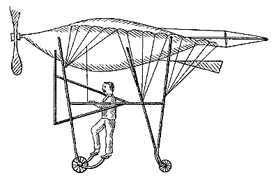
FIG. 62. -- GOUPIL -- 1883.
The alar spread was 19.68 ft. from tip to tip of wings, the length was 26.24 ft. from the head tip to the end of the tail, and the mid-section was 26 go sq. ft. in area, while the sustaining surface was no less than 290 sq. ft., the weight being 110 lbs.
It will be noticed that this was a marked departure from the ordinary aeroplane types, there being an ample body to contain machinery, and the wings being decidedly concavo-convex, while other inventors have generally endeavored to diminish the body as much as possible and to gain support from various combinations of plane surfaces.
M. Goupil's object was to make a series of preliminary experiments with this apparatus, in order to ascertain its stability, the effect of the wind upon such a system, and the resistance to be expected, as well as the sustaining power. He accordingly applied neither motor nor screw, but exposed it to the natural wind when blowing from 18 to 20 ft. per second, say, about 13 miles per hour, at which velocity the resulting air pressure is generally assumed to be 0.85 lbs. per square foot. These experiments took place in December, 1883, at which season the winds were quite variable, and the apparatus was anchored by various ropes so as to prevent it from rising more than 2 it. from the ground.
Exposed head on to a wind of 18 to 20 ft. per second, the body being inclined at an angle of 1 in 10 and the wings at 1 in 6 (about 10°), this apparatus lifted up clear of the ground the weight of two men besides its own, making a total of 440 lbs.! The thrust or end resistance did not exceed 17.6 lbs. M. Goupil tested this several times, and expresses himself as surprised at the low resistance to penetration against the wind evidenced by this apparatus, which was mounted upon two small wheels.
When the wind increased to more than 20 ft. per second he could no longer control the machine. There being no stays or guys to the wings, such as are shown in fig. 62 the apparatus was twisted out of shape, and the wind took greater effect upon the deformed side. Then a wind gust occurred; the efforts of five men were required to control the apparatus, and one of the wings (constructed with white pine) was broken.
The inclement season and other considerations of a personal nature prevented M. Goupil from pursuing these experiments further at that time. He had gathered valuable preliminary data, and had caught a glimpse of a very. important fact concerning the effect of concavo-convex surfaces, but his own affairs had a more immediate claim upon his personal attention.
He therefore desisted for a while and allowed the subject to remain in abeyance until he could take it up again, but he published, in 1884 a very remarkable book, "La Locomotion Aerienne," in which he advanced a number of important and new theoretical considerations concerning the solution of the problem of aerial navigation, gave data concerning the steam-engine, the condenser, and the various sizes of bird-like aeroplanes which he had designed, and generally evinced such a grasp and comprehension of the question that it seems a marvel that the book is not more frequently referred to by the French writers on aviation.
This experiment of M. Goupil opens up quite a new field of inquiry concerning the effects of concave, bird-like surfaces, when exposed to an air current. Calculated by the data which have been gathered by experiments upon plane surfaces, the "drift" and total resistance does not seem to vary greatly from what might be expected, but there is an enormous, an almost incredible increase of the lifting power.
Thus there was said to be a total end thrust of 17.6 lbs. in the apparatus when exposed to a wind of about 13 miles per hour, at which the air pressure would be presumably some 0.85 lbs. per square foot. The angle of incidence of the wings was practically 10°, and we may, without serious error, assume the resistance of the body to have been one-tenth of that due to its mid-section while that of the edges of the wings (presumably 0.20 ft in average thickness) would be about one-third of their plane cross-section. As the sustaining surface was 290 sq. ft., we then hare, using the table of ""lift"" and "drift" heretofore given, the following estimate:
RESISTANCE OF THE GOUPIL AEROPLANE.
Drift 10 290 X 0.85 X 0.0585 = 14.42 lbs.
Body 26.9 X 0.85 ÷ 10 = 2.28 lbs.
Edge of wings 19.7 X 0.2 X 0.85 ÷ 3 = 1.11 lbs.
Total 17.81 lbs.
which agrees closely with the amount said to have been ascertained by experiment; but when we come to calculate the lifting force we have:
Lift 10°--290 X 0.85 X 0 332 = 82 lbs.,
while the apparatus is said to have actually lifted 440 lbs., or more than five times as much!
Of course various allowances must be made in considering the results of an experiment carried on in a variable wind, and where so little motion of the apparatus 2 ft.) could be allowed. The thrust may have been measured while the breeze was steady, and the uplift to have occurred during a wind gust, deflected possibly by surrounding objects so as to produce a greater angle than 10° with the wings; still, in any case, the result of this experiment and also of other experiments by M Phillips , which are to be-described hereafter, leads to the inference that much greater supporting power is to be obtained from concavo-convex surfaces than from the flat planes which hitherto have been chiefly proposed for aeroplanes.
This increase in supporting power might indeed have been expected from the theoretical consideration: that the concave lower surface would produce a higher co-efficient of pressure, while the convex upper surface would deflect the current of air impinging at an acute angle thereon, and thus produce a partial rarefaction; and also from the much stronger practical consideration that this is the way the wings of birds are shaped; and yet very few experiments and proposals seem to have been made with bird-like aeroplanes.
This neglect may possibly be due to the fact that the proportions, the shape, the concavity and the convexity of natural wings differ from each other among the various species, so that the moment that we discard the flat plane, a multitude of combinations present themselves, which may require long and careful experimenting before the best shape for an artificial machine is ascertained.
It is understood, however, that M. Goupil has planned a whole systematic series of such experiments to elucidate this important matter, and that he hopes soon to be in position to carry them on.
In March, 1884 the Aéronaute published a paper by M. De Sanderval, giving an account of some very interesting experiments, which he had tried with a pair of artificial wings no less than 39 ft. across and 13 ft. wide in the middle. These wings formed an aeroplane, or rigid plane of canvas, stretched upon wooden arms, which latter, however, possessed a certain flexibility.
In a first set of experiments, this aeroplane, loaded with ballast to the amount of 176 lbs., was allowed to glide in calm air along a cable 1.300 ft. long, which both supported and guided it, and which was inclined at a slight angle. It was also allowed to drop in still air from a height of 131 ft.., and then still further experiments were tried with men riding on the machine when the wind was blowing.
For this purpose the aeroplane and its operator were suspended by a long rope from the middle of a cable, stretched in some cases between two hills and over a ravine, and in other cases between two high masts erected near the sea-shore.
M. De Sanderval states that he was attached some 5 ft. above the aeroplane and a little in front of its center of figure, so that by pulling upon four oblique cords he was enabled to shift his weight either forward or back, and to the right or left at pleasure.
When the wind blew and the apparatus was restrained by a head-rope, the effect was much the same as when gliding free in calm air, with, however, the unfavorable difference that when near the ground it was less steady by reason of whirling currents.
In a light wind the apparatus would rise until the suspending rope became horizontal, thus relieving it of its weight-carrying function, and the aeroplane would then oscillate at the pleasure of the operator.
When the wind increased to 18 miles per hour the apparatus would sustain the operator and two assistants.
Subsequently, M. De Sanderval gave an account of his experiments to the French Academy of Sciences, and this was reprinted in the Aéronaute for November, 1886 with the somewhat uncalled-for comment that "it is a pity that the author should not have stated the time, the place, nor the witnesses, as such extraordinary facts need verifying."
The following are the facts as stated:
My first apparatus consisted in two wings, each 1968 ft. long, thus giving an aggregate spread of 39.36 ft. by a maximum width of 13 ft. These wings were of canvas stretched upon bamboos and upon wooden arms. The canvas was divided into a series of parallel sheets or flaps, each 4 3/4 in. wide, and perpendicular to the dorsal l net They were suitably fastened, and a net was stretched above them, so that they might flap and open upon the upstroke, like the feathers of birds, which oscillate upon the quill which divides them into two unequal portions.Standing upright upon a light board, and connected by straps to a central spine, I was enabled by thrusts of the legs to develop their maximum effort; but with this apparatus, which worked quite well, I was enabled to settle but one fact, and that is, that man cannot develop sufficient energy to sustain himself in calm air. I therefore gave up the thought of beating wings.
I then rebuilt the apparatus, transforming the wings into a rigid plane, and replacing the flapping strips by an unbroken canvas.
This apparatus, weighing 99 lbs., and loaded with 176 lbs. of ballast, was caused to glide under a cable 1,300 ft. long, stretched between two bluffs. There was no deflection in the cable when the aeroplane glided across at speed, but the deflection was about 26 ft. when the apparatus was stopped in the middle.
If then released (by tripping a hook) it would at first drop almost vertically: then after the first second it would glide forward at increasing speed, while the rate of vertical fall diminished; but upon the slightest disturbance in the equilibrium, consequent upon any divergence between the center of gravity and the center of pressure, the inert ballast would aggravate the oscillation, and the apparatus would plunge down to smash. It seemed evident to me that if intelligence were applied to regulate the position of the center of gravity, steady progression would result.
I then suspended the apparatus by a long rope attached in the middle of the cable, and substituted my own person for the ballast. I found that with an intelligent live control the apparatus would oscillate in the wind according to my pleasure. as I have already indicated in a previous communication. The supporting surface of 301 sq. ft. sufficed to sustain a man at a comparatively slow rate of fall, and by a wind of 22 miles per hour it lifted me up wish two assistants, and sustained us in the air during the entire period that we kept the holding-back line taut, by maintaining a proper angle of incidence.
The last and more interesting experiment which I attempted was based upon these previous results, and also upon the fact that soaring birds can rise into the air on a helical path, or else maintain themselves a long while at the same altitude without beating their wings, provided always that they possess sufficient horizontal speed as regards the air. I therefore experimented with an apparatus somewhat similar to the preceding, but round in shape, suspended by a vertical rope 650 ft. long30, and caused it to swing around in a circle, so that the suspending rope described in its path the outer periphery of a cone. In this experiment I could feel a notable reaction against my weight, but it required a much longer suspending rope to allow so large an apparatus to swing in a circle of sufficient diameter to permit its gaining the necessary speed, and to manoeuvre freely. I believe, however, from the feeling produced upon my mind by the experiment, that I had really taken possession of space within the limits of my somewhat irregular speed, and also, from my observations of soaring birds advancing against the wind on rigid wings, that man can succeed in reproducing sailing flight.
If one had an unlimited height to fall in, affording plenty of time to think and to act, he would probably succeed in guiding himself at will. In calm air man does not possess sufficient energy to sustain himself, but either in a sufficient wind, or with a proper horizontal speed of his own, he finds himself under different circumstances, and derives from the air quite enough supporting power. It is through the operation of this dynamic equilibrium that he will eventually succeed in compassing practical flight.
I caused to be constructed, from manuscript notes furnished by M. Biot, a very ingenious apparatus intended to comply with the above conditions, and I experimented with it. This apparatus consisted in two great wings supported on a light carriage, which gained its initial speed by rolling down a long incline covered with an asphalt floor. It rose into the air pretty well, but always with the disadvantage that the experiment could not be suificiently prolonged to furnish decisive results; each time upon coming down the apparatus was injured.
It appears to me that a long, vertical rope, such as that previously described, swinging around so as to describe a cone of extended base, must afford greater chances for careful experiment and for eventual success.
The writer has been unable to find any further records of experiments by M. De Sanderval. He seems to have been bathed by the lack of means to maintain equilibrium, but even had he possessed the appliances and the skill to bring the center of gravity to coincide with the center of pressure, as often and as fast as the angle of incidence changed, it may be questioned whether he could have acquired, without a very long apprenticeship, that instinctive use of them which constitutes the science of the birds.
It is inferred from the description that M. De Sanderval experimented with plane surfaces, although it is possible that under the action of the wind they may have assumed those concavo-convex shapes which we have seen to obtain with the birds and to be more effective than flat planes. In any case, he is to be commended for having made an earnest: if unsuccessful effort to learn how to soar in a wind like a bird, the possibility of which performance for man will be further discussed hereafter.
In 1848 M. Armour the author of several papers which will be found in the reports of the Aeronautical Society of Great Britain, patented a flying machine, in which he proposed the use of aeroplanes or wings, oscillating upon springs transversely to the line of motion, these wings being set behind each other as well as superposed. It is not known whether any experiments were tried with this curious device, which seems to be a combination of fixed wings (or aeroplanes) with oscillating wings, but it seems doubtful that it can prove efficient.
There was a second aeronautical exhibition in 1885 under the patronage of the Aeronautical Society of Great Britain, but the total number of exhibits was only 16 as against 78 in 1868.
Among these exhibits the model which attracted most attention was that of M. C. Ring, of Denmark, which consisted of an aeroplane with a pair of arched wings, somewhat similar in the front-edge view to the arched wings of the gull and of the albatross. In plan, however, these wings were rectangular instead of the approximately triangular shape which obtains with the birds. These aeroplanes were to act as sustaining surfaces, the angle at which they met the wind being determined by the position of a large flat tail, and the propulsion being furnished by four wing-propellers oscillating beneath the aeroplane, and driven in the model by twisted rubber.
The apparatus was supported by a string fastened vertically above its center of gravity to the crosspiece of a light framework. It propelled itself slowly, but was incapable of free flight, probably in consequence of defective equilibrium.
M. Ring also exhibited a model of a gun-cotton engine in which small charges were to be exploded between two pistons, moving in opposite directions in a long cylinder; but the model was not a working one, and no attempt was made to construct a full-sized engine.
Reference has already been made to a "trunk steam-engine," shown by M. S. Hollands at this exhibition. He gave a description of this and of two other types of light steam-engines with which he had experimented, at subsequent meetings of the Aeronautical Society of Great Britain.
The first was a "direct-acting" engine, rotating at high speed twin vertical screw fans (right and left) in opposite directions, and a model of this machine, developing 1/16 horse power was said to have weighed 6 oz. for the engine and boiler, or at the rate of only 6 lbs. per horse power. It was first intended to generate the steam by burning liquid fuel, but M. Hollands subsequently concluded that hydrogen gas, carried highly compressed in a suitable reservoir, and burned with an admixture of twice its volume of air, would prove preferable for lightness and heating efficiency. He estimated that the weight of this type of motor, including not only the engine and boiler, but also the water therein, the fuel-gas reservoir and the driver's stand, would be 11.5 lbs.per indicated horse power.
The other engine was "geared" so as to rotate two right and left fans on concentric vertical shafts, one inside of the other, through the intervention of toothed -mitre gear. The function of these two vertically superposed fans was to lift only; a smaller horizontal fan being carried on a prolongation of the crank-shaft, and its thrust aided by the reaction of the exhaust steam ejected through a suitable nozzle. The weight of this engine per horse power is not stated.
Both these arrangements, it will be observed, involved discharging the exhaust steam into the air, and thus wasting some 20 to 22 lbs. of water per horse power per hour, M. Hollands not seeing his way to adding an aerial condenser (to recover the steam) in any form, within any admissible limits of weight. He stated that the power necessary was one indicated horse power for every 30 lbs. of the whole weight, so that without a condenser the flight of such an apparatus as he proposed would have been limited by the very small quantity of water which it could lift.
M. Hollands however, made some experiments on the best form of lifting screw-blades, and stated that he had found it advantageous to make the fan blade concave on the driving or lifting side, and that the angle of maximum efficiency was 15° with the plane of motion at the tip and 30° at the root. The form which he found most efficient was two-bladed; with the blades narrowest at the tips, slightly concave on the lifting side, the tip slightly drooping, each blade being approximately the shape of an elongated shallow spoon or scoop, and with a pitch equal to about two-thirds of the fan's diameter, giving a mean angle of blade of 22° 30' with the plane of motion. These blades were of thin sheet steel, and their forms will be noted as confirming what has already been stated as to the advantages of the bird-like form of wing. M. Hollands said further:
I find another advantage accrues also from the use of these very thin, sharp edged hollow blades--viz., that there is no appreciable resistance to rotation that does not contribute to lifting effect. A marked contrast to this desirable quality is presented in the results given by flexible bladed fans, constructed to vary their pitch automatically, being normally of coarse pitch (when still), but decreasing their pitch when rotated, and further decreasing it with increase of speed. Some experiments I made with fans of this description showed an unmistakable loss of power, as compared with the other type above described, due apparently to the energy absorbed in deflecting the elastic blades; which deflection, with a given speed, causes a constant strain and resistance, with no compensating useful effect.
In 1888 W. Beeson patented, in the United States, the singular soaring device shown in fig. 63. He had already patented, in 1881 a soaring apparatus consisting of two or more sets of adjustable superposed sails stretched on inverted A frames, which he expected to raise into the air like a kite, and then sail upon the wind, but he apparently abandoned this device in favor of the simpler form shown in fig. 63.
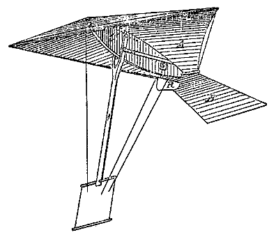
FIG. 63. -- BEESON -- 1888.
This consisted in a mainsail A and a tail or back-sail B, both of which were supported on a plate or board C, ranging fore and aft. This plate was convexed at its upper edge so that the sail A might extend over, forward and downward to a cross-bar forming the front edge, and thus enclose a head pocket to catch the wind. A forked pendulum-bar, I, was pivoted to the plate C, and it supported at its lower end a trapeze arrangement to carry the operator, who by means of three light cords extending to his hand might alter the angle of incidence of the mainsail A of the tail B, or of the rudder R. The mainsail and tail being, moreover, connected by an adjustable bar, which caused the mainsail to act upon the tail automatically, so as to maintain the equilibrium at all angles of incidence through the compound lever thus formed.
M. Beeson states in his patent that "this machine is self supporting in a light wind, say, of lo miles or more per hour, and that when once raised by a kite or otherwise, and cut loose, it will of itself perform the evolutions of a soaring bird and rise to any altitude."
The writer confesses that he has tried the experiment with a small model and has failed; and so, in the hope that some of his readers may be more fortunate, he has given this account of what seems to be a remarkably simple device--if it will work.
| List of Illustrations | Table of Contents | Index |