A novel form of flying machine has been devised by M. Henri Villard, a prominent engineer and aeronaut of Paris, who has carried on experiments in this direction for some time. His apparatus was exhibited at the last concourse of aviators, but as it was not entirely completed it could not be given a practical trial. The Villard aerostat embodies several different principles in the same apparatus, those of the kite, the parachute and the aeroplane, and part of it is given a gyroscopic motion, such as is exemplified in the well-known toy flier, the rapid revolution of which tends to keep it in the same plane so that is is almost impossible to overturn it. These principles are not contradictory, and may therefore be combined in an apparatus which will possess the advantages of the different forms. The principle of the flying machine may be best explained by imagining a parachute of considerable size and supposing that it is made rigid by an exterior steel rim and wire spokes. Again, if this parachute were attached by a cord, it would act like an ordinary kite. To propel the parachute in the horizontal direction a screw is added, operated by a suitable motor. In this case the apparatus, if started from an elevated point, will fall very slowly and will be enabled to cover a considerable distance from its starting point. One of the most original ideas is to add to the above combination the gyroscopic principle. This is brought about by causing the whole upper part of the parachute to turn rapidly, and as the rim is somewhat heavy this action becomes quite effective, and tends to keep the machine in one plane. In this way the apparatus acquires a great rigidity and it becomes difficult to overturn it. Another point is that the fall of the parachute may be almost or even quite overcome by arranging the upper part so as to give the surface the form of a very flat screw, just enough to compensate for the fall. In this way when the parachute revolves rapidly the descent becomes very slow, and it would no doubt be possible to overcome it entirely if desired. To complete the flying-machine it is only necessary to add a rudder and a seat for the aeronaut. One advantage it will have is that the aeronaut runs but little risk, for should the motor fail to work he will descend as in an ordinary parachute. The inventor has calculated the dimensions as well as the force which should be given to such an apparatus. As the whole machine, with the aeronaut, weighs from 650 to 750 pounds, he finds that according to a bird's proportions he should have about 52 square yards of surface. The form to be given to the screw is that which will overcome the air resistance, which in this case is very small, allowing a speed of 40 feet per second, and not more than 1/2 horse power would be needed; the inventor allows 4 horse power for the screw. To give a rapid revolution to the parachute requires also but a very small power; this, calculated on the proportions of a flywheel, is found to be about 2 horse power. As the parachute is also built on the plan of a helice, this will absorb, for the lifting, about 4 horsepower. For these three different operations he considers that 12 or 14 horsepower will be quite sufficient.

VILLARD'S
AVIATOR.
M. Villard has already constructed an experimental form of the apparatus, which is shown in the engraving, but expects to modify it considerably before carrying out the practical trials which he is to make next spring. The parachute, which embodies the gyroscope principle, is a large flat wheel, somewhat resembling a bicycle wheel, whose rim is made of a circular steel tube half an inch in diameter and very light. The wheel has an exterior diameter of 22 feet. It is attached to the upper and lower ends of a long hub by two sets of double steel pianowire spokes, with 100 pairs of wires in each set. The length of the hub is about 3 feet. The parachute covering is stretched upon the top surface; it is made of stout cotton balloon canvas and offers a resistance of 1,400 pounds per square yard. Below are placed the horizontal shafts of the screw and rudder, at a point calculated according to the resistance which the parachute offers to the air when in movement. The screw, made of canvas stretched upon wire frames, is composed of two similar halves; in front it has a small surface, but increases toward the rear until the whole has a complete half-turn of thread. It is driven by a horizontal shaft which passes to the center and there engages with the vertical shaft of the motor by a worm-gearing. The rudder, mounted in line with the screw, works in a forked support which allows it to turn in the vertical sense. It is directed by a horizontal shaft which engages with it below by a worm gearing. The shaft passes to the center and is there controlled by the aeronaut. To operate the gyroscopic portion and the screw a Buchet motor the two-cylinder type is used, operated by gasoline which is fed from the reservoir above. The motor gives normally 12 horse power and has 4-inch cylinder-bore and 4-inch stroke; it weighs about 130 pounds and works at 1,920 revolutions per minute. The motor which is seen on the left, is attached to a circular aluminium box surrounding the main shaft and containing the gearing and transmission devices for operating the whole apparatus. The box is mounted upon a cone-shaped piece whose point rests on the ground. The aeronaut sits upon a small movable seat, mounted upon two horizontal rods and has at hand the various steering and controlling levers and the hand-wheel of the rudder.
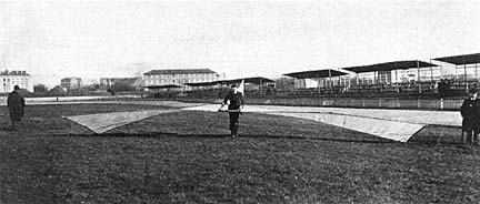
DEMOUVEAUX
AVIATIOR.
Originally appeared in Scientific American, 86, March 8, 1902, p. 173. No mention was made of the Demouveaux craft, though the photograph appeared with the Villard article.
sbck/htgb